AVEVA E3D DESIGN 3.1.11 (Complete Smart Workflow from Setup to Export) Download
by Ali Haider · May 16, 2026
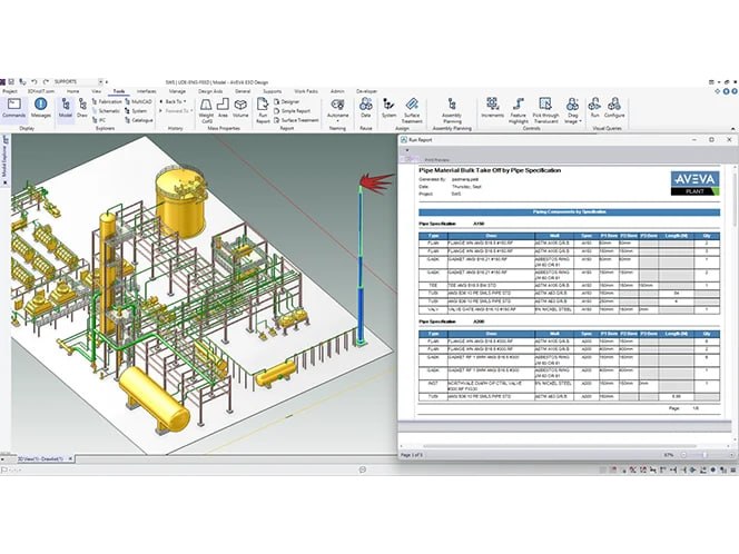
Table of Contents
ToggleSummary
AVEVA E3D DESIGN 3.1.11 is a powerful, professional-grade 3D design system for the plant, marine, and power industries. Unlike standard CAD software, it is built around a database-driven architecture that enables multiple users to work simultaneously on large-scale projects. Learning E3D requires understanding its hierarchical data structure, mastering command line controls, and adopting disciplined workflows for modeling and drawing extraction.
The key to success with E3D is structured learning. Start with the Admin module to understand project setup. Practice creating simple equipment and piping in a training project. Learn the most common command line shortcuts. Gradually add complexity with structural modeling, clash detection, and drawing extraction. Use companion tools like the 3Dfindit plugin for equipment models and Navisworks for comprehensive clash detection.
Initial Setup
Installing and configuring AVEVA E3D DESIGN correctly from the start is critical because the software relies on a complex ecosystem of databases, catalogs, and project hierarchies. Unlike standard CAD applications that you can simply install and launch, E3D requires a structured environment before you can start modeling.
System Requirements: Before installation, ensure your workstation meets the recommended specifications. E3D is a resource-intensive application designed for large industrial projects. You will need a modern multi-core processor (Intel Xeon or Core i7/i9), a minimum of 16GB RAM (32GB recommended for complex projects), a professional-grade graphics card (NVIDIA Quadro series), and an SSD for faster database access.
Installation Process: The installation involves multiple components. You will need to install the main E3D DESIGN application, the Catalog and Specs databases, and the license management software. E3D uses a licensing system that typically connects to a network license server managed by your organization’s IT department.
Project Hierarchy Understanding: Before creating your first project, understand how E3D organizes data. The hierarchy follows this structure: World → Site → Unit → Zone → Element. A World contains entire project data. Sites represent geographical locations or major plant areas. Units break down sites into functional sections. Zones further divide units for specific disciplines (piping, equipment, structural). Elements are the individual 3D objects you create. Understanding this hierarchy is essential because everything you model must sit within this structure.
Project Creation and Configuration: To create a new project, open the Admin module. Select “Create New Project” and define the project name, location, and naming conventions. You will need to configure access control and user roles for team members. Each discipline (piping, equipment, structural, electrical, HVAC) will need appropriate permissions. The system also requires setting up model databases and catalog databases before any modeling begins.
Understanding The Dashboard
E3D DESIGN uses a multi-window interface that differs significantly from common CAD software. When you first launch E3D, you will see several distinct areas.
Model Explorer (Tree View): On the left side of the screen, the Model Explorer displays your project hierarchy. This shows all sites, units, zones, and elements in a tree structure. Clicking any item in the tree focuses the 3D view on that element. You can right-click items to access properties, modify visibility, or delete elements. This is your primary navigation tool for finding specific components in large projects.
3D Graphical View: The central area is the 3D viewport where you create and manipulate models. E3D uses a three-button mouse control scheme. The left button selects objects. The middle button rotates the view. The right button opens context menus. Holding Shift while using the middle button pans the view. Holding Ctrl with the middle button zooms.
Command Line: At the bottom of the screen, you will find the command line. This is a critical feature for experienced users. You can type commands directly instead of navigating menus. For example, typing “NEW EQUIPMENT” followed by Enter starts the equipment creation process. Typing “CE” (Create Equipment) is a common shortcut. Learning these commands dramatically speeds up workflow.
Toolbars and Menus: Along the top and sides are toolbars organized by discipline. The Pipe toolbar contains piping commands. The Equipment toolbar contains commands for creating vessels, pumps, tanks, and other equipment. The Structure toolbar contains commands for steel and concrete. The Draft toolbar contains drawing extraction commands. You can customize which toolbars are visible based on your role.
Draw List: Below the Model Explorer, the Draw List shows all drawings and views associated with the current selection. This is where you manage 2D drawing extraction from your 3D model.
Creating First Project
Your first project in E3D should be a simple one to learn the workflow. Let’s create a small equipment model with basic piping.
Step 1: Set Up Your Environment: Launch E3D DESIGN. Log in using your credentials. The login screen asks for your username, password, and project selection. If this is your first time, select the training project or a newly created test project.
Step 2: Navigate to the Correct Zone: In the Model Explorer, expand the hierarchy until you find the Zone where you have permission to model. For training projects, there is often a “Training” zone or “Equipment” zone. Select the zone by clicking it.
Step 3: Create Equipment: Click the Equipment toolbar. Select “Create Vertical Vessel.” The command line will prompt you for the origin point. Click anywhere in the 3D view to place the vessel. A dialog will appear asking for vessel dimensions. Enter a diameter of 1000mm and a height of 3000mm. Click Apply. The vessel appears in the 3D view.
Step 4: Create a Nozzle: With the vessel still selected, click “Add Nozzle” from the Equipment toolbar. The command line asks for the nozzle position. Type “E” (East) and press Enter. Enter a diameter of 150mm. Enter a projection length of 200mm. Click Apply. A nozzle appears on the east side of the vessel.
Step 5: Create a Pipe: Switch to the Pipe toolbar. Click “Create Pipe.” The command line asks for the starting point. Click on the nozzle face you just created. The command line now asks for the direction. Type “N” (North) and press Enter. Enter a length of 2000mm and press Enter. Type “U” (Up) and press Enter. Enter a length of 1500mm. Press Enter twice to finish the pipe. You have now created a simple pipe connected to the equipment nozzle.
Step 6: Save Your Work: Unlike automatic saving in modern applications, E3D requires explicit saving. Type “SAVE WORK” in the command line or click File → Save. Your model is now saved to the project database.
Common Workflow Steps
A typical E3D DESIGN workflow follows a logical progression from modeling to drawing extraction. Understanding this workflow helps you plan your work efficiently.
1. Equipment Modeling: The first step in any plant design project is placing major equipment. This includes vessels, tanks, pumps, compressors, heat exchangers, and other process equipment. E3D provides parametric equipment creation tools where you enter dimensions and the software generates the 3D geometry. For standard equipment, you can also import from manufacturer catalogs using the 3Dfindit plugin, which provides access to thousands of manufacturer-approved equipment models.
2. Piping Design: After equipment is placed, you route piping between equipment nozzles. E3D’s piping module uses a spec-driven approach. You select a piping specification (which defines pipe material, pressure rating, and component types), then route pipes by specifying start points, end points, and direction changes. The software automatically selects appropriate fittings (elbows, tees, reducers) based on the spec.
3. Structural Modeling: For pipe racks, equipment supports, and platforms, you create structural steel models. E3D includes a structural module with standard steel sections (I-beams, channels, angles, tubes). You place members by selecting start and end points or by using grid systems.
4. Clash Detection: After completing modeling, you run clash detection to find interference between different disciplines. Clash detection checks if pipes intersect with structural steel, if equipment interferes with other equipment, if cable trays conflict with piping. E3D highlights clashes in the 3D view, and you can generate clash reports for resolution.
5. Drawing Extraction: The Draft module extracts 2D drawings from your 3D model. You create views (plan views, elevation views, section views), add dimensions, and generate isometric drawings for piping. The Plot command exports drawings to PDF, DXF, or prints directly. The format options include PRINT (for physical printers), DXF (for CAD export), and PDF (for documentation).
Exporting Files
AVEVA E3D DESIGN supports multiple export formats for collaboration with other software and stakeholders.
PDF Export: To export a drawing to PDF, use the Plot command. In the command line, type: PLOT AREA PDF /filename.pdf Replace “filename” with your desired name. The software generates a PDF of the current view. This is useful for sharing drawings with clients or team members who do not have E3D access.
DXF Export: For exporting 2D drawings to other CAD software, use the DXF format. Type: PLOT AREA DXF /filename.dxf This produces a basic DXF export. For more configuration options, use the LIEXEC command instead. DXF exports are compatible with AutoCAD and other CAD applications.
Navisworks Export: For 3D model review and clash detection across multiple disciplines, export your model to Navisworks format. This is done through the File → Export → Navisworks menu. The exported NWC or NWD file can be opened in Navisworks Freedom (free viewer) or Navisworks Manage.
Isometric Drawing Export: Piping isometric drawings can be exported as DXF files. In the Draft module, select the isometric drawing you created, right-click, and choose Export → DXF. These isometric drawings are used by fabricators to manufacture pipe spools.
3D Model Export: The entire 3D model can be exported to STEP or IGES format for use in other CAD systems. This is useful when collaborating with equipment suppliers or contractors who use different software.
Troubleshooting
E3D DESIGN users commonly encounter specific errors, especially when starting. Here are the most frequent issues and their solutions.
“No Branch Table Entry” Error: This occurs when you try to route a pipe but the specification does not contain a matching branch component (tee or olet). Solution: Check your piping specification. The branch table must include entries for the branch size and header size combination you are attempting. You may need to modify the spec in the Catalog module or select a different spec.
“Element Not Found” Error: This appears when the software cannot locate a referenced element. This often happens after importing data or when working with models created by other users. Solution: Run the “VERIFY” command on the affected zone. This checks all references and reports broken links. You can also use the “RECONCILE” command to fix common reference issues.
“Cannot Create Connection” Error: This happens when you try to connect a pipe to equipment but the nozzle specification does not match the pipe specification. Solution: Verify that the nozzle size and rating match the pipe size and rating. Check that both components use compatible end types (flanged vs. welded).
Slow Performance: If the 3D view becomes sluggish, you may need to adjust display settings. Turn off “Shadows” and “Reflections” in the View menu. Use “Zone View” instead of “Full Model” to limit display to a specific area. Increase the “Culling Distance” to hide objects far from your current view.
License Checkout Failed: This error indicates the software cannot connect to the license server. Solution: Check your network connection to the license server. Verify that other users on your team can access licenses. If the server is down, contact your IT department. You may also have a license reserved by another user.
Drawing Extraction Produces Blank Output: If your extracted drawing is empty, the view may not have been properly set up. Solution: Return to the Draft module, regenerate the view using “REGEN VIEW”, and ensure the view range correctly captures your model. Check that the view orientation is correct (Plan, Elevation, Section) .
Productivity Tips
Once you master the basics, these tips will dramatically increase your efficiency in E3D DESIGN.
Learn Command Line Shortcuts: Every menu action has a corresponding command line entry. The most useful shortcuts include: “CE” for Create Equipment, “CP” for Create Pipe, “PCE” for Position Equipment, “CONN” for Connect Pipe to Equipment. Keep a cheat sheet of common commands until they become muscle memory.
Use Templates for Standard Components: If you repeatedly create similar equipment (e.g., identical pumps or vessels), create a template. Model the equipment once, save it as a template file, then use the “Import Template” command to place copies in new projects. This saves hours of repetitive modeling.
Master the CE Command for Equipment: The Create Equipment command has options you might miss in the toolbar. Typing “CE /P” creates a parametric vessel where you can specify dimensions after placement. Typing “CE /C” creates equipment from a catalog component. Typing “CE /T” creates equipment from a template.
Use the Compare Tool: When working in teams, use the Compare Tool to see what changed between model versions. This is essential for understanding modifications made by other designers. The tool highlights added, modified, and deleted elements.
Set Up Macros for Repetitive Tasks: If you perform the same sequence of commands repeatedly (e.g., creating a specific pipe support arrangement), record a macro. Type “RECORD MACRO” to start recording, perform the commands, then “END MACRO” to save. Play the macro with “PLAY MACRO” followed by the macro name.
Use Attribute Mapping for Drawings: When extracting drawings, spend time setting up attribute mapping. This automatically populates title blocks with project information, revision numbers, and dates. Once configured, drawing extraction becomes a one-click operation.
Enable Auto-Save Reminders: While E3D does not have auto-save, you can set up reminder pop-ups. In the Settings menu, enable “Save Reminder” and set the interval to 30 minutes. This prompts you to save regularly, preventing data loss from unexpected crashes.
Best Companion Tools
AVEVA E3D DESIGN works best when integrated with complementary tools that extend its capabilities.
AVEVA PDMS: If your organization is migrating from PDMS to E3D, you can run both systems in parallel during transition. E3D can directly read PDMS databases, allowing you to access legacy projects without conversion. Migration tools help transfer catalog data, specifications, and user permissions.
AVEVA ERM (Engineering Reference Data Manager): ERM manages engineering data across the entire project lifecycle. It integrates with E3D to ensure consistency between the 3D model and engineering datasheets, instrument indices, and line lists.
Navisworks: The Navisworks exporter is essential for multi-discipline clash detection. While E3D has built-in clash detection, Navisworks provides more advanced reporting and review features. Export your model regularly to Navisworks for comprehensive review meetings.
3Dfindit Plugin: This free plugin provides access to thousands of manufacturer equipment models directly within E3D. Instead of modeling every pump, valve, or instrument from scratch, you can download accurate manufacturer models. Search methods include geometric similarity, sketch search, and color search.
AVEVA Diagrams: This tool integrates P&IDs (Piping and Instrumentation Diagrams) with the 3D model. When you select a pipe in the 3D model, AVEVA Diagrams highlights the corresponding line on the P&ID, and vice versa. This ensures consistency between schematic and physical design.
Microsoft Excel: For bulk data entry, E3D supports Excel import. You can create equipment lists, nozzle schedules, and pipe line lists in Excel, then import them directly into E3D. This is much faster than manual entry for large projects.
Alternatives to the Software
While AVEVA E3D DESIGN is an industry leader, several alternatives exist for plant and marine 3D design.
AVEVA PDMS: E3D is the successor to PDMS, but PDMS remains in use at many facilities. PDMS has a steeper learning curve and less modern interface, but it is stable and proven. Organizations with large PDMS legacy databases often continue using PDMS while planning migration to E3D.
Intergraph Smart 3D: Hexagon’s Smart 3D is E3D’s primary competitor. Smart 3D offers similar capabilities for plant design with strong rule-based modeling. It uses a different data structure (Object-Oriented vs. E3D’s hierarchical approach). Smart 3D is popular in North America, while E3D has stronger presence in Europe and Asia.
AutoCAD Plant 3D: For smaller projects or organizations with limited budgets, AutoCAD Plant 3D is a lower-cost alternative. It runs on the AutoCAD platform, so learning is easier for existing AutoCAD users. However, it lacks the advanced database management and multi-user collaboration features of E3D.
SolidWorks with Routing: For equipment and piping design in smaller facilities, SolidWorks with the Routing add-in provides 3D modeling capabilities. This is suitable for skid-mounted systems or small process plants but does not scale to large industrial facilities.
Bentley OpenPlant: Bentley’s OpenPlant offers similar plant design capabilities with strong interoperability with other Bentley infrastructure products. It is often chosen by organizations already using Bentley for civil or structural design.
Conclusion
AVEVA E3D DESIGN is not a software you master in days. It requires weeks of focused learning and months of practical experience to achieve proficiency. However, the investment pays off through dramatically improved productivity on large industrial projects. The ability to extract accurate drawings, generate bills of materials, and coordinate across disciplines makes E3D an essential tool for serious plant design organizations. For those committed to a career in industrial 3D design, E3D skills are highly valued and transferable across employers worldwide.