CopperCAM Latest 2025 Powerful Software Download
Download the CopperCAM Latest 2025 from this link…
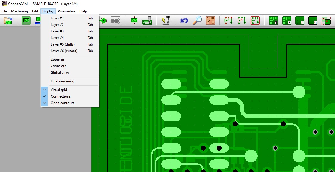
![]()
Summary
When I first worked with CopperCAM, I was impressed by how smoothly it handled engraving, drilling, and milling for PCB prototypes. Using Windows XP, Vista, or even the 2000 and 2003-S versions, the Software loaded Gerber and Excellon files without any hiccups. I often relied on its automatic and manual alignment tools to match layers, and its real-time display made spotting equipotential paths and isolation contours easy. Whether dealing with pads, tracks, or text, the hatching and hatches features helped in removing unwanted copper while keeping fine details intact. I frequently switched between G-code, HPGL, Isel-NCP, RDGL, and Roland outputs, thanks to the customisable post-processor.
Even with multiple zones, polygons, macros, and negative polarity, the system’s management tools and library of cutters kept my workflow efficient, especially when planning boring cycles or support bridges for cut-out contours. One feature I particularly value is its driver flexibility. I could send output to COM or LPT ports, connect to external drivers, or chain directly to a virtual machining setup. The edition and correction options let me fine-tune diaphragms, contour shapes, and even centreline texts. Having a native 32-bit processor helped when aligning card outlines or plotting simple yet precise paths. Even when dealing with the removal of dense surfaces or clearing tight areas, auto-snap ensured accuracy.
The sequence of opening containing layers, plotting references, checking holes, and sending data made my workflow predictable but adaptable. From enforcement of spacing to addition of final tracks, every step felt under control, whether I was working on maximum board sizes or smaller, more intricate designs.
Preparing and Organizing PCB Projects
Working with CopperCAM has taught me that precision in drills, engraving, and exporting is as much about smart preparation as it is about having the right software. When I first began, I didn’t realize how important it was to create proper alignment and centering before any drilling or cut-out operations. Now, I always check my layers, tracks, and contours against the Gerber and Excellon formats to ensure compatibility. The calculated results are only as good as the data you feed in, so I keep a habit of saving a back-up of every project in a safe directory like C:\Program Files and Documents to avoid problems if I ever need to reinitialise or remove installations.
Ensuring Security and Smooth Installation
I’ve learned the hard way that not every website offering PCB tools is trustworthy. Once, an Avast warning popped up with a URL: Blacklist message while I was downloading an update, which left my workstation blocked from certain sources. Following Best Practice recommendations, I now buy my licence directly from verified sources. I also make sure my installation is secured and has the right privileges, especially if administrator’s rights are needed for write-operations. Having suggestions from experienced users helped me disable unnecessary functions and delete unused files, keeping my disk safe and my system running smoothly.
Customizing Settings for Better Output
One of my personal workflow improvements is customizing the COPPERCAM.INI and COPPERCAM.TOO files to match my current project’s parameters. I’ll add specific colours for layers, tweak scales for thin tracks, and isolate polygon surfaces or ground-planes when needed. For larger jobs with thousands of holes or drillings, I split them into smaller sessions to stay within time-limits and keep output consistent. I also export generated files in RS274-X format, ensuring they’re valid for import into other systems without problems.
Maintaining Efficiency Over Time
Over time, I’ve had to remove temporary additions, delete old settings, and write new ones based on manual analysis of the output. In one case, a secure server hosting my files failed, but because I had provided a postal and nominative address during registration, I was able to recover my licence and keep upgrading without delays. I keep Dozens of tools in my toolset, and having a simple naming system for keys and icons has saved me countless hours. Whether it’s tweaking variations, managing number constraints, or adjusting conditions for test runs, I’ve found that staying organized and creating efficient processes is what makes CopperCAM work at its best for me.
Defining Tools and Parameters
When I first started using CopperCAM for my printed-circuit projects, I quickly learned how important it was to set the right parameters. The tools I kept in my rack had different characteristics, from smaller drill bits for precision work to greater diameter cutters for fast removal. The program’s functions make it simple to define each tool, give it a name, and assign it to tasks like isolation, hatching, contouring, and drilling. Adjusting depth, margins, and motion speed allowed me to avoid a break in delicate epoxy materials. I even used boring cycles for oversized holes, though I learned to respect the limit of what each tool could handle without risk.
Setup and Task Assignments
Setting up a program for milling involves both selected and assigned tools. I often indicate the number of drills needed, choose strategies, whether single passes or multiple cycles, and ensure plots and lines are aligned. The mesh density in zones can be controlled through hatch spacing, which greatly affects the recovery between paths. One trick I’ve found useful is to keep distance margins slightly larger for engraved text to keep it crisp.
Output and File Handling
For Output, CopperCAM gives several formats, including definable post-processor types that link directly to the milling machine. Once a file is produced, it can be sent to printers, virtual drivers, COM or LPT port connections. I’ve had times when the output was overwritten because I forgot to give it a name, so now I make sure it’s added before running the program. If the software prompted me with a command line argument, it was usually because the driver needed direct access for engraving operations.
General Work Sequence
The General Work Sequence starts by opening a Gerber or Excellon file from my CAD application, often with layers for both tracks and pads. CopperCAM can detect the track net for a card’s final cut and neutralise unused tracks. I like that it can calculate isolation contours around pads, which can be rectified by inserting, removing, or adding hatched zones. In RS274-X format, references like diaphragms are applied automatically, but when they are missing, the dialogue box lets me complete them manually.
Streamlined Workflow
Over time, I’ve memorised my predefined settings so CopperCAM loads them automatically, avoiding the need to redefine pad shapes or references each time. My workflow now is smooth, calculate, apply, check results, and produce the output without extra deleting or loading steps. It’s a balance between automation and manual refinement, but the process keeps my cards consistent and precise.
If you want to Purchase KeyGen Activator / Cracked Version /License Key
Contact Us on our Telegram ID :
Join Us For Update Telegram Group :
Join Us For Updated WhatsApp group:
Crack Software Policies & Rules:
You Can test through AnyDesk before Buying,
And When You Are Satisfied, Then Buy It.
Lifetime Activation, Unlimited PCs/Users.